Projects, techniques and thoughts involving microcontrollers, electronics & robotics for the hobbyist.
Tuesday, September 16, 2014
Fairydust
The Story of My Obnoxiously Bright LED Jacket
Burning Man. The most awesome experience ever. My story begins last year, which was the first time I went. Long story short, having been a little unprepared, I was just about the darkest creature on the playa (one of the most typical things about Burning Man is that at night everybody and everything is lit up beautifully). I had a head lamp to keep cyclists from running me over. Me of all people! So for this year I decided to over-compensate. Inspired by a super-bright LED that I saw at work, I decided I'm going to make an LED jacket that would be seen from a distance and will blind anyone that's standing close. Mission accomplished :)
This jacket has 48 super-high-brightness (150 lumen) variable-color LEDs integrated in it. The LED color are created by a controller that is installed on the wrist. The controller has a little graphic display and a rotary push-button that allow selection from different available patterns. Some of those patterns react to sound in real-time. The jacket is powered by two integrated battery packs weighing a total of about 1kg and lasting for over 12 hours of typical usage.
I've designed and hand-made all the electronics and software and sewed the actual jacket over a few months in my not-so-spare time.
The Attire
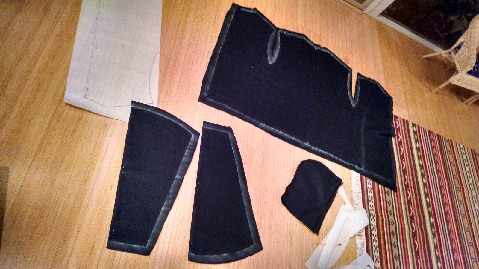
Extracting the pattern from an existing jacket
This is by far the most advanced sewing project I've ever done. It includes a 5-piece pattern (that I had reverse-engineered from an existing jacket) times two layers. The outer layer is black felt with fine glitter. The inner layer is black fleece. All the electronics go in between, so the jacket looks clean and feels smooth from both the outside and the inside. The jacket features a hoodie and a separating zipper. In order to allow washing of the jacket as well as easy repair of the electronics, everything can be detached and re-attached: the connection between the two layer as well as between the electronics and the fabric are all implemented using hook-and-loop fasteners (Velcro). Each LED is mounted on a small PCB that is attached to the inside of the outer fabric layer. Only the LED itself is visible from the outside, through a 5mm hole. The hole is reinforced (on the inside) with a fusible (iron-on) female Velcro, also serving for mounting the PCB, which has a male Velcro glued to it. The controller is attached in a similar fashion, with the display and control knob picking through matching holes. Two battery packs are carried inside specialized flame-proof inner pockets that are attached near the waist.
Marking the fabric with a chalk
The cut pieces for one of the layers
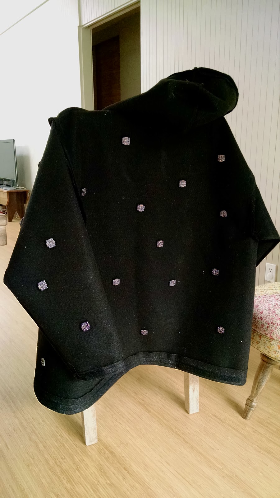
Complete jacket, prior to mounting electronics
All in all, it was an amazing experience to design the jacket and make it. I'm very pleased with the result too. To my untrained eye it looks not much different in quality than a jacket that you might see in a store.
LED Modules
LED modules, top and bottom
It started with finding these amazing 3W RGB LEDs on eBay that cost $30 / 50 pieces. Sold! My idea was to make modules around them that allow them to be daisy-chained. Controlling a large number of LEDs would require a hell-of-a-lot wiring if had to run 4 wires (R, G, B, GND) from the controller to each LED! So the standard solution is to daisy-chain them. In other words, each LED is connected to the next until the last one is connected to the controller. Particularly popular with the Maker crowd are the WS281x series LEDs (more commonly known as "Neo-Pixel") that can be daisy-chained with as little as three wires by using a cleverly designed single-wire serial protocol. I decided to use the same technique, maybe even to make something that's compatible with the WS28', only 50x more powerful.
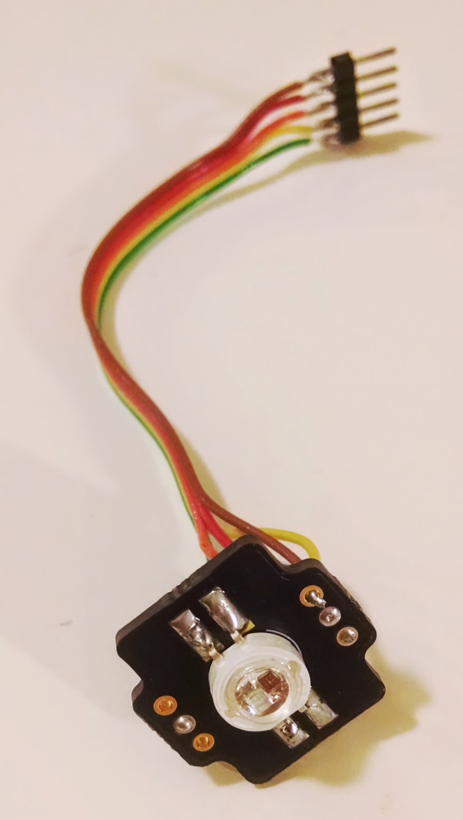
Having considered different approaches (including using the WS2811 and boosting its current), I eventually opted for having a little MCU (PIC12F1571) on each module as well as 3 discrete constant current drivers. My goal was to optimize for cost (I made 50 of these, so every dime matters) while maintaining a nice feature set. I managed to reduce the cost to about $3/module at quantity 50, which is pretty good I think.
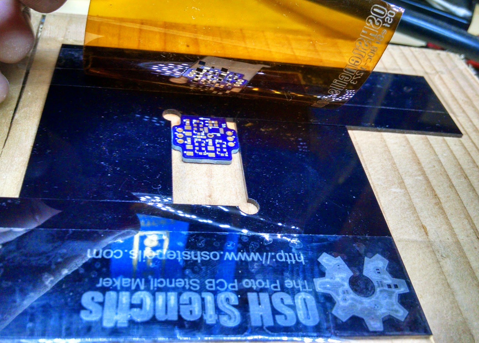
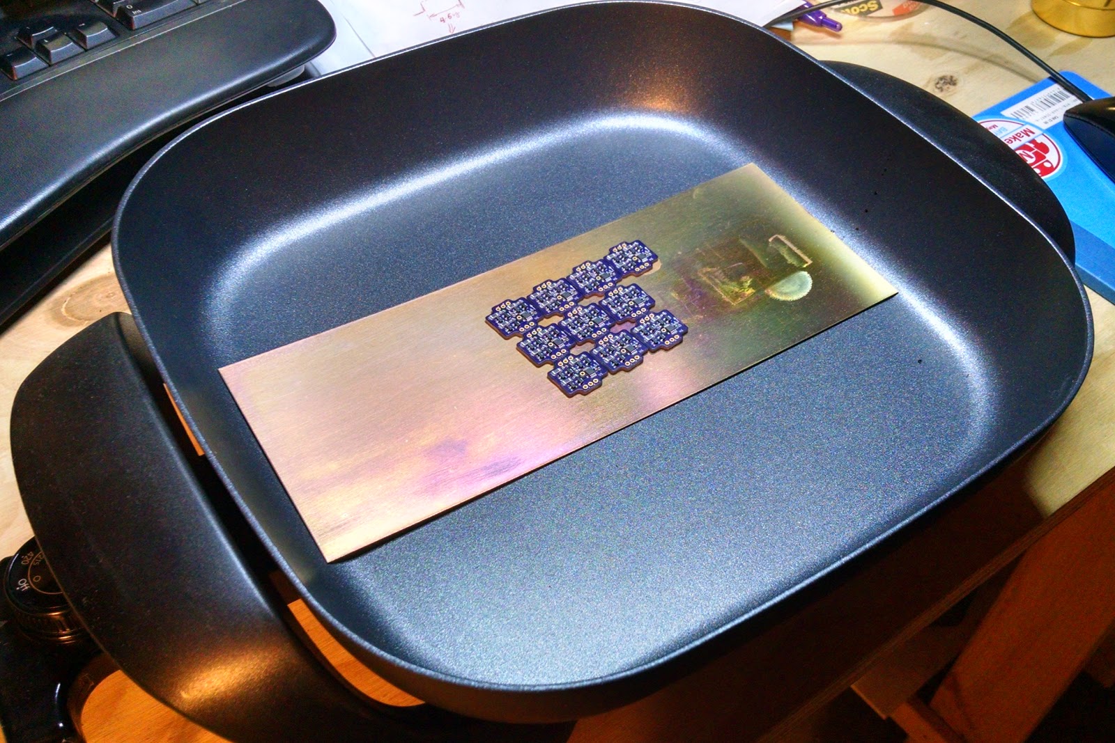
The boards were made at OSH Park (awesome!!!) Making 50 of something is not like making 1 or 2. Soldering by hand is prohibitively slow (around 20 small parts on each module). I've been wanting to try poor-man's reflow soldering for a while now, so this was a good excuse. Big shout out to OSH Stencils (surprisingly unrelated to OSH Park) that make cheap solder paste stencils in small quantities and fast. The stencil is a piece of Kapton film that is placed on top of the bare PCB and has precision-cut holes in all the places where solder should be applied. A simple jig makes alignment of the stencil with respect to the PCB fast and accurate. A single swipe of a squeegee puts solder paste on all the pads. Then the components were manually placed with tweezers. This has now become by far the most time-consuming step of the process. Once the components are all in place, several modules at a time can be put on a hot electric skillet. Shortly, the solder paste melts and all the components are cleanly soldered to their pads. That easy. 100% yield after the first batch that easily revealed what I should look out for when applying the paste (answer: apply some pressure on the squeegee to keep the stencil tight against the board and the paste layer as thin as the stencil). The LEDs were the only part soldered by hand on the opposite side of the board. I think I'm going to use this technique a lot going forward: the extra few bucks for the stencil are totally worth the time savings and superior quality of the product.
An LED module on the solder paste jig
The stencil is perfectly aligned with the PCB
Reflow soldering a batch of LED modules on a skillet
Check out the quality of the solder joints!
These 8-pin MCUs are awesome! At 50 cents a piece they feature 3 channels of 16-bit PWM, an on-die temperature sensor and 8MIPS without an oscillator over a wide voltage range. They implement the serial protocol in software (bit-banging), running at 800kbps. 3 of the MCU pins are each connected to a constant current driver (comprising a FET, a BJT and a shunt resistor), feeding current to each of the Red, Green and Blue LEDs. Constant current is important for getting a consistent color that is not affected by fluctuation of supply voltage, variation of the LEDs, etc. Since the LED modules are dissipating a lot of heat (5W at full brightness), they can get dangerously hot if left on for long. Thus, I used the on-die temperature sensor to shut down if the temperature exceeds 60°C. Another protection feature is to handle cases of software malfunction or loss of communication with the controller. For that purpose I've used the hardware watchdog on the PIC, so that if we don't successfully decode a new command for 2 seconds, we reboot (and as a side-effect turn the LED off).
First assembled LED module, instrumented for firmware development
The serial protocol is pretty simple and clever: "zeros" and "ones" are represented by pulses of different widths (durations) on the wire. Each node in the chain consumes the first 24-bits it receives to be its own color, then echoes any following bits to the output (connected to the next node in the chain). When the line is silent (neither zeros nor ones) for a certain duration (milliseconds), all nodes latch at once (i.e. set the color of the LED to the given command and start listening for a new command again). In order to meet the high bandwidth requirements (they translate to allowing long chains at good refresh rates), I wrote assembly interrupt handlers with carefully calculated timing.
Once I had everything ready and tested, I wired 48 modules in a long chain using silicon-insulated wires. These wires are very flexible and durable.
Many LEDs
First test of daisy-chaining
Every little task becomes time consuming at large quantities
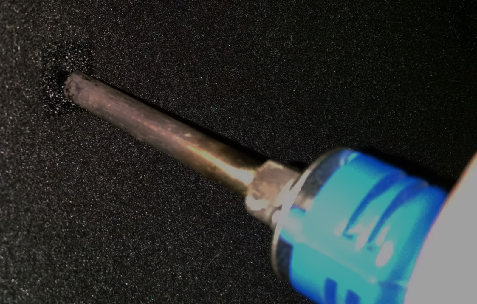
Making holes for the LEDs using a soldering iron
The module is attached to the inside with only the LED peeking through the hole
Outside close-up view of an LED
All LED modules attached (jacket is inside out) prior to wiring
Outside view with all the LEDs attached
Power System
Buck regulator PCB
The LED modules are all designed for a 5V operation. Each LED module takes around 1A when fully on. I designed the power system so that it is able to deliver up to 5A continuously. In other words, I had to constrain my software so that the maximum current is not exceeded. I designed a buck regulator module around the TPS54560 chip. One of the nice features of this chip is that it is pretty easily configurable for different input and output voltages, current limit, etc. So the module I designed and the spare board I now have can easily be used on my next project. Power is supplied by two 2S LiPo packs with 5Ah capacity, for a total of about 75Wh. Under normal usage this can easily last all night on a charge. The two packs were connected in series to form a 4S pack with a nominal voltage of 14.8V. I've also joined the balance connector of the packs, so the battery interface looks exactly like an off-the-shelf 4S pack despite the fact that it is split in two (for ergonomic reasons). I also hooked up a cheap off-the-shelf LiPo voltage indicator / buzzer alarm to be able to constantly monitor the cell voltage and protect against over-discharge.
Buck module, hardened and ready to go
For safety reasons, I mounted the batteries inside safety LiPo pouches made out of thick flame-proof silicon fabric. The pouches where Velcro'ed to the inside of the jacket so that if worst comes to worst (in extreme cases LiPo batteries can ignite), I can quickly remove them from my body.
Controller
Controller mounted
Just for the hell of it, I wanted the controller to be somewhat fancy. I resisted my initial urge to make a IOIO-based controller, because I wanted the jacket to be 100% standalone. I did, however, use the same MCU that's used on the IOIO, both because it's awesome and because I'm very familiar with it and I have many of them lying around the house. The controller board features:
A PIC24FJ256DA206 MCU.
A 128x32 pixel, white OLED display module that I got from eBay on the cheap. It talks to the MCU over SPI.
A rotary + push encoder (knob that can be either turned or pushed) for input.
A tiny microphone with some analog magic circuitry that extracts the audio envelope on a logarithmic scale. The output is fed to an analog input.
A 3-axis accelerometer. It talks to the MCU over I²C.
An output for the LED chain, which also powers the controller.
Several extension ports (digital, analog, I²C, UART, etc.) - I have some ideas for improvements :)
Being all spoiled from the LED modules, I've ordered a stencil for that one too, even though I only needed one. It was up and running in no time.
I chose to use an RTOS to facilitate easy authoring of the software while maintaining a very low power consumption when the LEDs are not running. FreeRTOS was a natural choice for me, as it is free and also very familiar to me. There are two main tasks: the higher priority task reads the microphone and controls the LEDs at 50 frames per second; the lower priority task handles the UI (display + knob). The UI presents a list of available LED animations that can be scrolled through by turning the knob and activated by pressing it. I developed a framework that makes it very easy to author new animations, so it was then easy to quickly make about 20 such programs with different feels. Most of them are random in nature because I like this style.
An animation gets a reading of the audio level and acceleration on every frame in case it wants to react to any of them. Due to lack of time, I ended up not implementing the accelerometer feature.
Controller front (OLED, knob, microphone)
Controller back
Aftermath
Off to Black Rock City, NV (where Burning Man lives)! The jacket was a huge success. A lot of people came over to compliment, ask questions and takes pictures. One of the first people who saw me passing by with my "Mr. Pink" animation (fast random blinks of shades of red / pink / white) said: "Hey! This is so cool! You look like you're leaving a trail of fairy dust behind you". From that moment on I shall be know on the Playa as Fairydust!
As with every project, not everything went perfectly. The LED modules are not as robust to their noisy power lines as I had hoped, so every once in a while one of them might suddenly have the wrong color on for a split second. However, I think the general idea was good. I'm considering making another revision on those modules and perhaps offer them as a product (think super-bright drop-in replacement for NeoPixels). If you're interested, drop me a comment below and it will increase the likelihood that I'll actually get myself to do this.
And last, I've now started working on a scaled-down version (lower power, simpler, lower cost) to use as magician costumes for my kids for Halloween.
At its current state it is not worth sharing, as some improvements are needed for better noise immunity. I'm considering actually making another revision, which I'll happily share once it's ready and proved reliable.
Can you tell us a little more about the constant current drivers on the pixel nodes? Are they all hardware based or is there some firmware involved using the DACs? Also, is that a copper sheet in your skillet? I assume to help spread the heat evenly. Thanks!
The constant current drivers are 3 copies of a simple circuit, similar to this one: http://i.stack.imgur.com/5sKPR.png It is hard-wired to regulate to about 350mA. Different intensities are achieved by PWM. The PIC12 that I'm using has a 16-bit PWM, which I'm running at about 400Hz. About the copper - exactly right. Without actually confirming that there's a problem to work without it, I assumed that because of how the heating elements are laid out the temperature might not be consistent. The copper plate attempts to mitigate that.


Can you share the schematic of the led boards?
ReplyDeleteAt its current state it is not worth sharing, as some improvements are needed for better noise immunity. I'm considering actually making another revision, which I'll happily share once it's ready and proved reliable.
DeleteCan you send schematic of the led boards to me too?
DeleteCan you tell us a little more about the constant current drivers on the pixel nodes? Are they all hardware based or is there some firmware involved using the DACs? Also, is that a copper sheet in your skillet? I assume to help spread the heat evenly. Thanks!
ReplyDeleteThe constant current drivers are 3 copies of a simple circuit, similar to this one:
Deletehttp://i.stack.imgur.com/5sKPR.png
It is hard-wired to regulate to about 350mA.
Different intensities are achieved by PWM. The PIC12 that I'm using has a 16-bit PWM, which I'm running at about 400Hz.
About the copper - exactly right. Without actually confirming that there's a problem to work without it, I assumed that because of how the heating elements are laid out the temperature might not be consistent. The copper plate attempts to mitigate that.